Flexibility of a Flex Circuit
Whether they are used in surgical instruments, mobile phones or automobiles, flex circuits provide the flexible functionality and space-saving design that these devices need. However, there are a few things to keep in mind when designing a flex circuit to maximize flexibility, performance and reliability.
One of the most important factors in determining a flex circuit’s flexibility is the material used. Several options are available for a flex circuit: Polyimide, PET and Polyetheretherketone (PEEK). Polyimide is the most common for generic flex circuits due to its good thermal stability, chemical resistance and elongation properties. The other two options are more expensive but offer specialized properties. Choosing the right material for your specific application depends on a careful trade-off of performance, cost and schedule.
The thickness of the flex circuit material is also a major factor in determining its flexibility. Thicker materials are more rigid and less prone to bending. On the other hand, thinner materials allow for greater flexibility and are more economical. Depending on the specific application, you may be required to use a thicker flex circuit or a thinner one. If the device must be very durable or have high electrical performance, a thicker flex circuit is the best option.
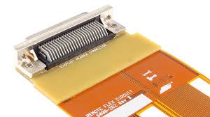
Key Factors Affecting Flexibility of a Flex Circuit
Another critical aspect of a flex circuit is the placement of components. It is recommended that components not be placed next to each other because they could create interference or cause a short circuit. This will improve the overall quality of the flex circuit and help it to last longer.
The layout of a flex circuit should be carefully considered, as it is not as structurally stable as a rigid PCB. It is important to use a design tool with a built-in rules engine that will prevent errors during the layout process. This will ensure that the flex circuit can be successfully manufactured.
It is also important to use a PCB editor with design rules that will restrict via placement to areas of the flex circuit that will not bend. This will reduce stress on the copper that will occur during bending. It is also advisable to use a hatched copper pattern that will reduce stress on the traces during tight radius bends.
When designing a flex circuit, it is also necessary to make sure that all the edges of the board are rounded to avoid sharp angles. This will reduce the risk of the flex circuit breaking during assembly or in use. Additionally, it is important to have large bend radiuses for flex circuit traces. This will help to avoid stress that could break the copper conductors.
Finally, it is essential to choose a manufacturer that offers turnkey services for PCB fabrication and assembly. This will reduce the risk of miscommunication between different vendors and help to ensure that the final product meets your requirements. A reputable manufacturer will have advanced manufacturing and testing capabilities that can guarantee the highest quality for your flex circuits. In addition, they should have a long history of working with customers to meet their unique design and production needs.